Verilog Notes
Verilog is a type of Hardware Description Language (HDL) used for define digital circuits. Another HDL commonly used is the systemverilog (a superset of verilog, fully backward compatible with verilog) and VHDL (Very High-Speed Integrated Circuit Hardware Description Language).
These languages are used to design and model hardware, such as FPGAs and ASICs. It describes the behavior of digital systems for simulation and allows these descriptions to be "synthesized" into actual electronic circuits.
Resources
- UC Davis 281 Verilog Handout
- Verilog Quick Reference Guide by Stuart Sutherland
- nandland verilog tutorial
- Verilog Practices
- Torpor module examples generator
- Chipverify
- Verification Guide
- 小梅哥论坛
- 小梅哥B站
- FPGA中文资源
Module
Modules are the fundamental building blocks for verilog, it encapsulates a specific piece of functionality.
`timescale <time_unit>/<time_precision>

module <module_name>([ports]);
  // Module content

endmodule;
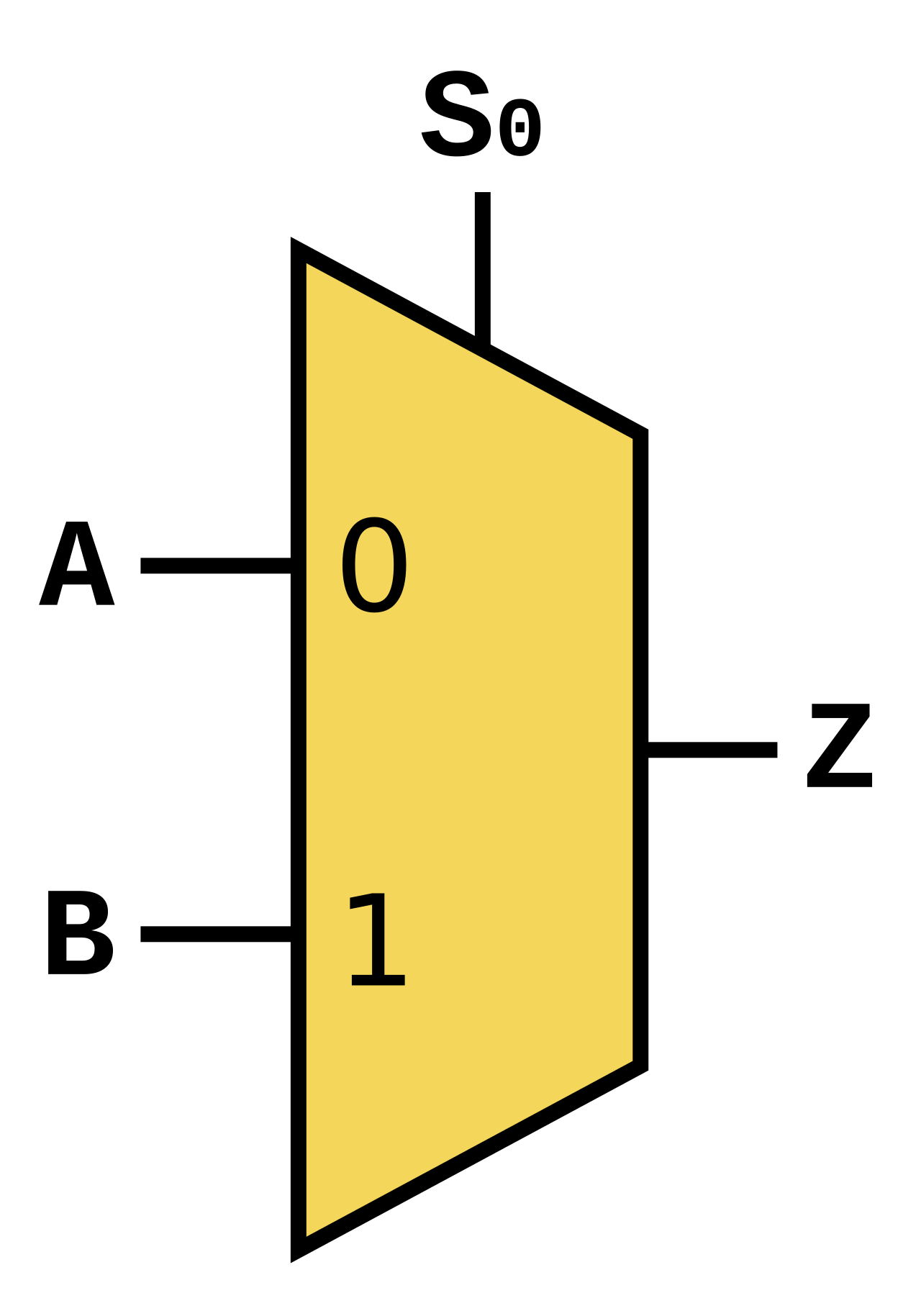
Example of Multiplexer Module
| Multiplexer | Verilog Code of Multiplexer |
|---|---|
Multiplexer by Cburnett, licensed under CC BY-SA 3.0. | Multiplexer |
Testbench
A Verilog testbench is a self-contained Verilog module used to verify the functional correctness of a design, referred to as the Device Under Test (DUT).
`timescale 1ns/1ps

module <module_tb>;

  // DUT connections

  <module_name> <module_instance>(
      <link DUT to module ports>
    );

    initial begin
      <Testbench contents>
    end

endmodule
Example: Testbench for Multiplexer
`timescale 1ns/1ns

module mux_tb();
  reg s_a;
  reg s_b;
  reg sel;
  wire out;

  mux mux_test(
    .a(s_a),
    .b(s_b),
    .sel(sel),
    .out(out)
  );

  initial begin
    s_a = 0;
    s_b = 0;
    sel = 0;
    #200  // Delay 200ns

    s_a = 0;
    s_b = 1;
    sel = 0;
    #200

    s_a = 0;
    s_b = 0;
    sel = 1;
    #200

    s_a = 0;
    s_b = 1;
    sel = 1;
    #200

    s_a = 1;
    s_b = 0;
    sel = 0;
    #200

    s_a = 1;
    s_b = 1;
    sel = 0;
    #200

    s_a = 1;
    s_b = 0;
    sel = 1;
    #200

    s_a = 1;
    s_b = 1;
    sel = 1;
    #200
  end
endmodule
We can then run the simulation on our module.